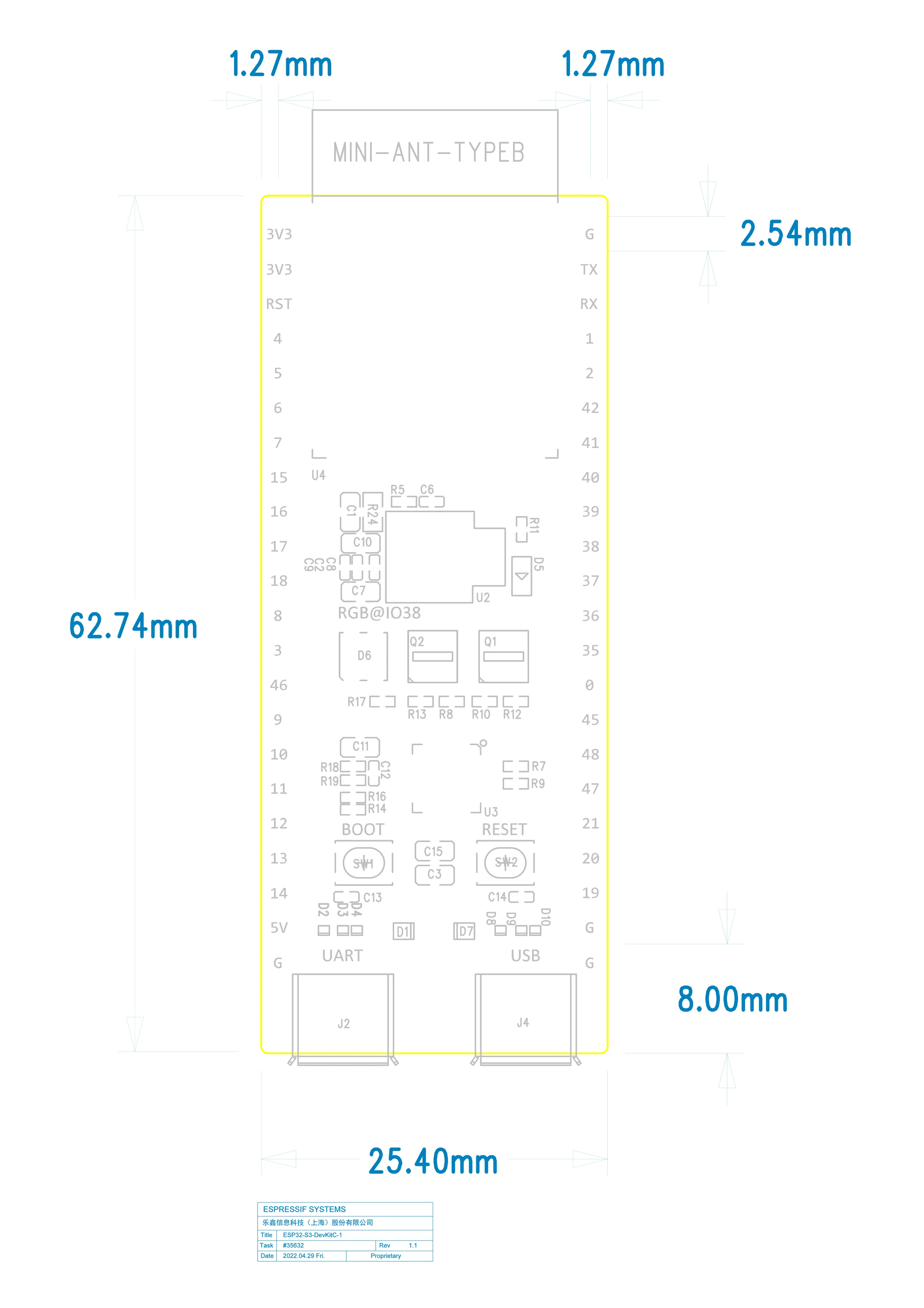
The ESP32-S3-DevKitC-1 exposes GPIO pins on two 22-pin headers (J1 and J3).
| Pin | Label | GPIO | Function | Notes |
|---|
| 1 | 3V3 | - | Power | 3.3V output |
| 2 | 3V3 | - | Power | 3.3V output |
| 3 | RST | CHIP_PU | Reset | Active low reset |
| 4 | 4 | GPIO4 | ADC1_CH3 | Touch, RTC |
| 5 | 5 | GPIO5 | ADC1_CH4 | Touch, RTC |
| 6 | 6 | GPIO6 | ADC1_CH5 | Touch, RTC |
| 7 | 7 | GPIO7 | ADC1_CH6 | Touch, RTC |
| 8 | 15 | GPIO15 | ADC2_CH4 | Touch, RTC |
| 9 | 16 | GPIO16 | ADC2_CH5 | Touch, RTC |
| 10 | 17 | GPIO17 | ADC2_CH6 | Touch, RTC |
| 11 | 18 | GPIO18 | ADC2_CH7 | Touch, RTC |
| 12 | 8 | GPIO8 | ADC1_CH7 | Touch, RTC |
| 13 | 3 | GPIO3 | ADC1_CH2 | Touch, RTC |
| 14 | 46 | GPIO46 | - | Input only |
| 15 | 9 | GPIO9 | ADC1_CH8 | Touch, RTC |
| 16 | 10 | GPIO10 | ADC1_CH9 | Touch, RTC, FSPI |
| 17 | 11 | GPIO11 | ADC2_CH0 | Touch, RTC, FSPI |
| 18 | 12 | GPIO12 | ADC2_CH1 | Touch, RTC, FSPI |
| 19 | 13 | GPIO13 | ADC2_CH2 | Touch, RTC, FSPI |
| 20 | 14 | GPIO14 | ADC2_CH3 | Touch, RTC |
| 21 | 5V | - | Power | 5V input/output |
| 22 | G | GND | Ground | |
| Pin | Label | GPIO | Function | Notes |
|---|
| 1 | G | GND | Ground | |
| 2 | TX | GPIO43 | U0TXD | UART0 TX |
| 3 | RX | GPIO44 | U0RXD | UART0 RX |
| 4 | 1 | GPIO1 | ADC1_CH0 | Touch, RTC |
| 5 | 2 | GPIO2 | ADC1_CH1 | Touch, RTC |
| 6 | 42 | GPIO42 | - | JTAG MTMS |
| 7 | 41 | GPIO41 | - | JTAG MTDI |
| 8 | 40 | GPIO40 | - | JTAG MTDO |
| 9 | 39 | GPIO39 | - | JTAG MTCK |
| 10 | 38 | GPIO38 | - | RGB LED V1.1 |
| 11 | 37 | GPIO37 | - | PSRAM (N8R8/N16R8) |
| 12 | 36 | GPIO36 | - | PSRAM (N8R8/N16R8) |
| 13 | 35 | GPIO35 | - | PSRAM (N8R8/N16R8) |
| 14 | 0 | GPIO0 | - | Boot strapping |
| 15 | 45 | GPIO45 | - | VDD_SPI strapping |
| 16 | 48 | GPIO48 | - | RGB LED V1.0 |
| 17 | 47 | GPIO47 | - | - |
| 18 | 21 | GPIO21 | - | - |
| 19 | 20 | GPIO20 | USB_D+ | USB-OTG D+ |
| 20 | 19 | GPIO19 | USB_D- | USB-OTG D- |
| 21 | G | GND | Ground | |
| 22 | G | GND | Ground | |
Pin Restrictions
Strapping Pins
These pins have special functions during boot:
| GPIO | Strapping Function | Default |
|---|
| GPIO0 | Boot mode | Pull-up (normal boot) |
| GPIO45 | VDD_SPI voltage | Pull-down (3.3V) |
| GPIO46 | ROM messages | Pull-up (enable) |
| GPIO | Notes |
|---|
| GPIO46 | Cannot be used as output |
USB Pins
GPIO19 and GPIO20 are used for native USB:
| GPIO | USB Function |
|---|
| GPIO19 | USB D- |
| GPIO20 | USB D+ |
Peripheral Mapping
ADC Channels
| ADC | GPIO Pins |
|---|
| ADC1 | 1, 2, 3, 4, 5, 6, 7, 8, 9, 10 |
| ADC2 | 11, 12, 13, 14, 15, 16, 17, 18 |
Touch Sensors
Most GPIO pins (1-14) support capacitive touch sensing. These are useful for touch buttons without external components.
JTAG Debug
| GPIO | JTAG Function |
|---|
| GPIO39 | MTCK |
| GPIO40 | MTDO |
| GPIO41 | MTDI |
| GPIO42 | MTMS |
SPI Interfaces
FSPI (default SPI pins):
| Function | GPIO |
|---|
| FSPI_CLK | GPIO12 |
| FSPI_MOSI | GPIO11 |
| FSPI_MISO | GPIO13 |
| FSPI_CS | GPIO10 |
I2C (Any GPIO)
I2C can be mapped to any available GPIO. Common defaults:
| Function | Suggested GPIO |
|---|
| SDA | GPIO8 |
| SCL | GPIO9 |
UART
| UART | TX | RX |
|---|
| UART0 | GPIO43 | GPIO44 |
| UART1 | Any | Any |
| UART2 | Any | Any |
Visual Pinout Diagram
Common Configurations
Minimal Sensor Project
GPIO4 → Temperature sensor
GPIO5 → Humidity sensor (I2C SDA)
Display + SD Card
GPIO10 → SPI CS (Display)
See Also