Board Dimensions
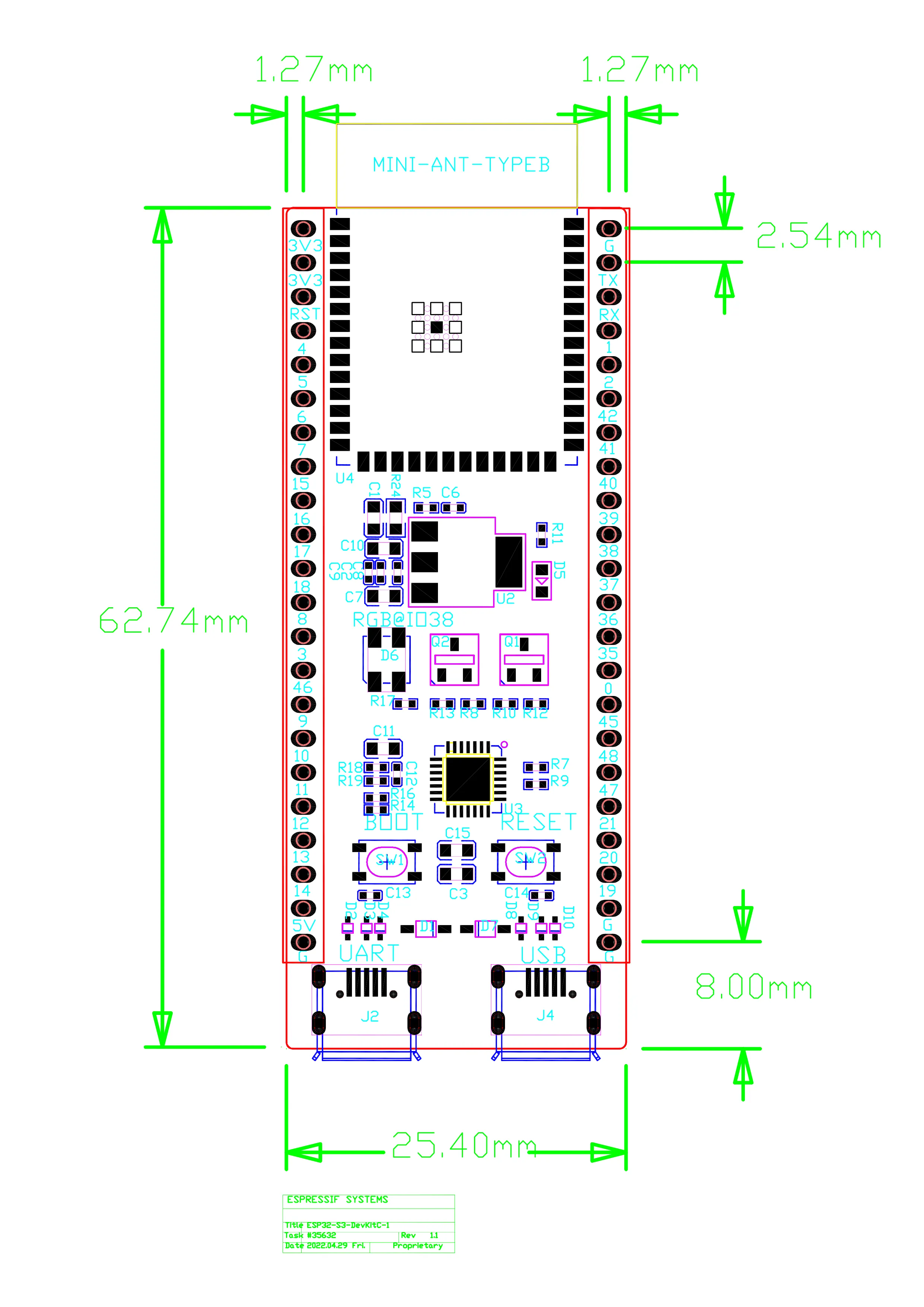
Primary Measurements
| Parameter | Value (mm) | Value (inches) |
|---|
| Board Length | 62.74 | 2.47 |
| Board Width | 25.40 | 1.00 |
| PCB Thickness | 1.6 | 0.063 |
| Total Height | ~8.0 | ~0.31 |
| Parameter | Value |
|---|
| Header Pitch | 2.54 mm (0.1”) |
| Pin Spacing | 1.27 mm (0.05”) |
| Header Row Spacing | ~22.86 mm |
| Pins per Side | 22 |
USB Connector Position
| Parameter | Value |
|---|
| USB Offset from Board Edge | 8.00 mm |
| USB-UART (J2) Position | Bottom end |
| USB-OTG (J4) Position | Top end |
Module Dimensions
ESP32-S3-WROOM-1
| Parameter | Value |
|---|
| Length | 25.50 mm |
| Width | 18.00 mm |
| Height | 3.20 mm |
| Antenna Extension | 0.91 mm beyond module |
Breadboard Compatibility
The DevKitC-1 is designed for standard breadboards:
| Feature | Compatibility |
|---|
| Header Pitch | Standard 0.1” |
| Row Spacing | Spans center gap |
| Recommended Breadboard | 830-point (63+ rows) |
Enclosure Design Guidelines
Keep-Out Zones
| Area | Clearance | Reason |
|---|
| Antenna Area | 15 mm minimum | RF performance |
| USB Connectors | 5 mm front | Cable access |
| Buttons | 3 mm clearance | Finger access |
| LED | 2 mm clearance | Visibility |
Recommended Enclosure Internal Dimensions
| Dimension | Minimum | Recommended |
|---|
| Length | 65 mm | 70 mm |
| Width | 28 mm | 32 mm |
| Height | 12 mm | 15 mm |
Mounting Options
No Built-in Mounting Holes
The DevKitC-1 does not include mounting holes. Consider these alternatives:
-
Header-Based Mounting
- Use header pins for mechanical support
- Insert into female headers on carrier board
-
Adhesive Standoffs
- Apply self-adhesive standoffs to bottom
- Available in various heights
-
3D-Printed Brackets
- Custom brackets gripping board edges
- Can include antenna clearance
-
PCB Carrier Board
- Design custom carrier with mounting holes
- Female headers for DevKitC-1 insertion
3D Model Reference
For CAD integration, the DXF file contains the board outline:
DXF_ESP32-S3-DevKitC-1_V1.1_20220429.dxf
Key Features in DXF
- Board outline perimeter
- Header pad locations
- USB connector footprints
- Module placement outline
Component Heights
| Component | Height Above PCB |
|---|
| WROOM-1 Module | 3.2 mm |
| USB Connectors | 2.8 mm |
| Buttons | 2.0 mm |
| Headers (unpopulated) | 0 mm |
| Headers (standard male) | 8.5 mm |
| Headers (standard female) | 8.5 mm |
Weight
| Configuration | Weight |
|---|
| Board Only | ~6 g |
| With Male Headers | ~10 g |
| With Female Headers | ~10 g |
Thermal Considerations
Heat Dissipation
The module generates heat during:
- High-power Wi-Fi transmission
- CPU-intensive operations
- Extended PSRAM usage
Recommendations
| Condition | Consideration |
|---|
| Enclosed Operation | Ensure ventilation near module |
| High Ambient Temp | Consider active cooling above 60°C ambient |
| Peak Current | LDO thermal limits at 500mA continuous |